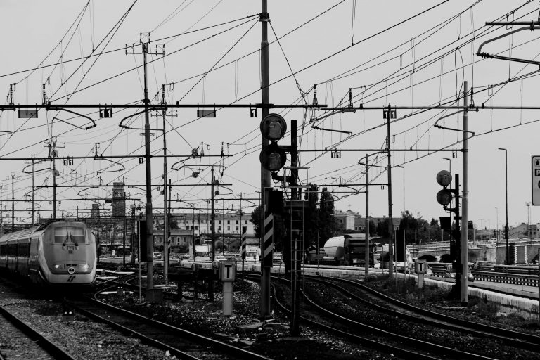
The electrification of a fleet involves either a third rail or an overhead catenary system typically. Achieving appropriate current collection in a high-speed train needs the contact wire geometry within defined limits. This aim is usually achieved by supporting the contact wire from a second wire known as the messenger wire (in the US & Canada) or catenary (in the UK). This wire approximates the natural path of a wire strung between two points, a catenary curve, thus the use of “catenary” to describe this wire or sometimes the whole system. This wire is attached to the contact wire at regular intervals by vertical wires known as “droppers” or “drop wires” or “hangers”. It is supported regularly at structures, by a pulley, link or clamp. The whole system is then subjected to mechanical tension by auto-tension devices [1].
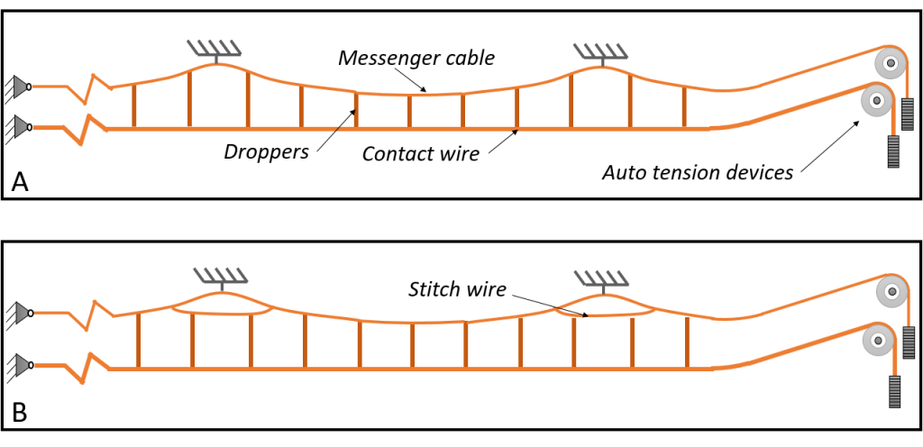
In Germany, most of the catenary systems (Oberleitung) have stitch wire. For example, according to siemens design, in DC lines, Sicat HD has stitch wire, and in AC lines Sicat SR, Sicat SA and Sicat HA have stitch wire as well. The following figure shows the static model of catenary with and without stitch wire.
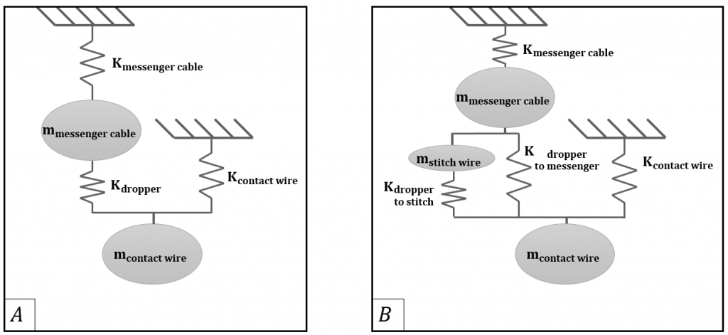
In this figure, K messenger cable and K contact wire are stiffness matrix of messenger cable and contact wire respectively. The values of these matrices are a function of the tension of each cable and the stiffness of the supports of each cable, which can be calculated according to [2]. Kdroppers is a matrix which has the stiffness of each dropper on the main diagonal. m messenger cable and m contact wire are vectors which describe the equivalent mass of messenger cable and contact wire (plus all attached mass such as clamps, etc) at connection points of droppers for messenger cable and contact wire respectively. Similar definitions govern on stitch wire.
Any change in the tension of contact wire or messenger cable leads to a change in values of K messenger cable and K contact wire and change the initial configuration of the catenary. Auto-tension device keeps the tension of contact wire or messenger cable “semi-constant”. Usually, the working range of auto-tension devices is between the upper and lower tension limit [3].

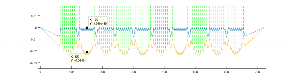
According to [2], it is possible to estimate the initial configuration of catenary after any change in the tension of the contact wire of messenger cable. The following figure shows the configuration of catenary after a 10% reduction in the tension of the contact wire.

Then, the effect of 5% tension loss in messenger cable has been studied in the following figure.

It is interesting to know that the tension loss in messenger cable is several times more distractive that tension loss in contact wire. By 10% reduction in the tension of contact wire, the maximum change in vertical position of contact wire is less than 1 mm. But when the tension of messenger cable is reduced by 5%, the vertical position of contact wire change around 20mm. It shows that the performance of auto-tension devices in messenger cable (catenary cable) is more important and should be monitored in a shorter period.
The following section is added on 19.01.2020 based on comments on this article
In some design of catenary, The tension of contact wire and catenary cable is applied by one auto-tension device. The proposed simulation approach can simulate this case, as well. The results show that in this case, the friction in tension wheel is as important as the friction in the tension wheel of messenger cable when the tension of the contact wire and catenary cable is independent. The following figure shows the 5% reduction in both contact wire and messenger cable.
Furthermore, there is one point which has not been considered in the simulation. It is assumed the tension keeps constant along the messenger cable and contact wire, while The longitudinal component of resistant forces at masts, make a change in tension along messenger cable and contact wire which is illustrated in the following figure.
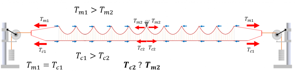
But still, there is one open point, can we say estimate that which one is bigger? T_c2 or T_m2
6 responses to “Which one is more critical? tension loss in contact wire or messenger (catenary) cable”
what about the equalising plate at the Balance weights susley this keeps to 2 wires at the same tension
You are right, but the auto tension devices (tension wheels) are not 100% perfect. For example, siemens allows 50kg deviation in tension due to tension wheel.
So we are talking about the cases which the tension wheel doesn’t work well and I trayed to prove that monitoring the performance of the tension wheel of messenger cable is essentially important.
The tension loss effects are experienced more greatly near the middle of a tension length far away from the auto tension devices during the temperature extremes. The balance plate will equalise the tension between contact and messenger at terminations across the temperature range, as opposed to systems with twin tension devices (one for the contact and one for the messenger) where a slight variation between separate tension devices can be expected. This said, the effects of tension loss along the tension length toward the midpoint will continue to be there regardless of tension device setup as it is dependent on the length of wire and track geometry.
For the same magnitude of tension loss on each wire, it is the tension loss on the messenger wire that presents the worse outcome for the overall system due to the variation in contact profile caused by the change in tension of the messenger.
Thank you, Matt, for your comment. That was interesting for me to know that the tension in cables is not constant in a mechanical section. I tried to show your point in a figure at the end of the article.
Dear Frank, I went through to you comment and I made a new simulation to find out the answer of you question. I did 5% reduction in the tension of both contact wire and catenary cable which you can see the effect at the end of the article now. The catenary configuration in simulation is selected based on the reference model of EN 50318. I you need to know the effect of tension change on your sepecified catenary, let me know please.